


 9 / 170

ASCO CARBON DIOXIDE INC | 5409 Highway Ave. | Jacksonville, FL 32254 | T +1 904 278-6503 |
ascoco2.comVersion 3.3 (02/18)
9
ASCO CO
2
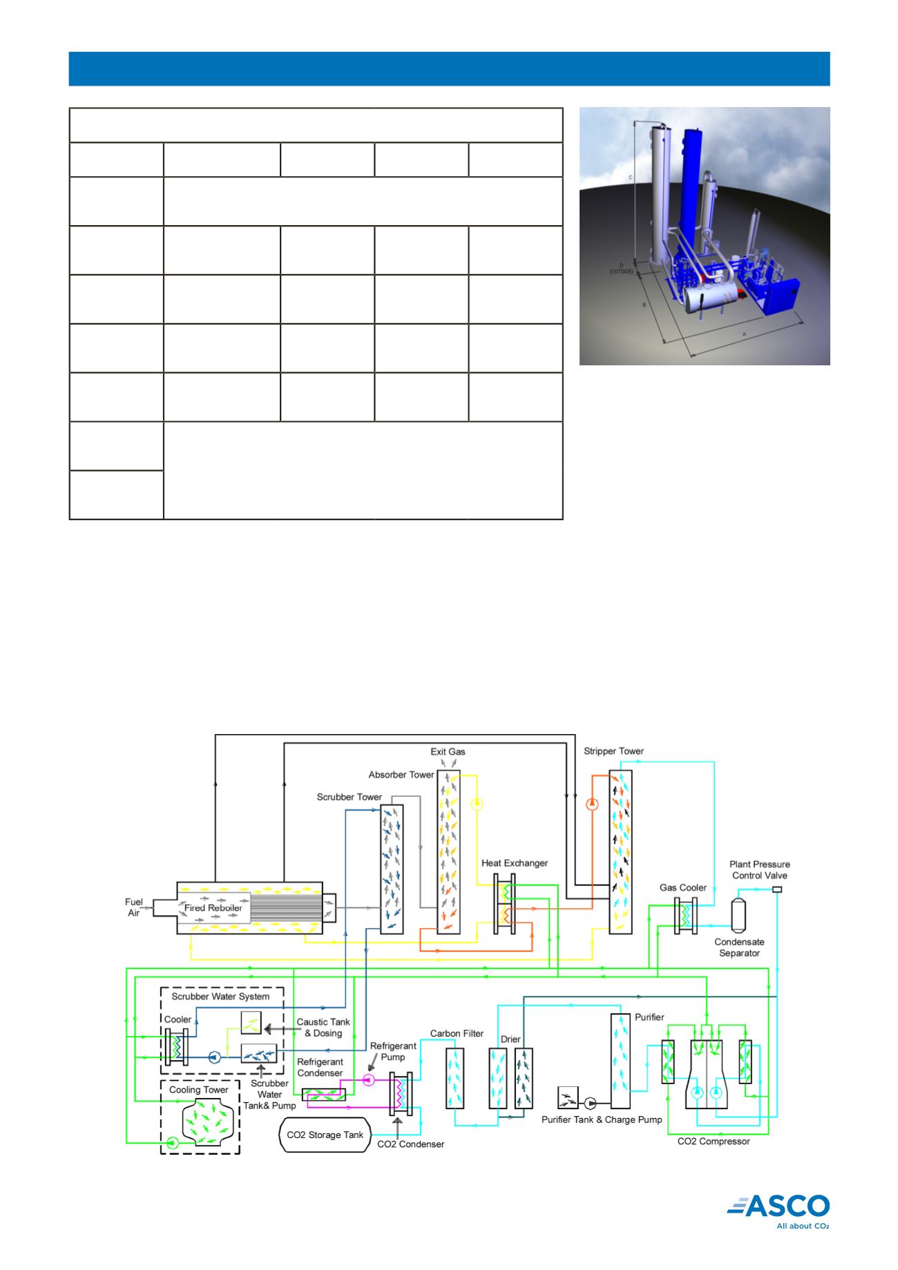
Production Plant process description
The fuel is burned under carefully controlled conditions. After water/soda ash scrubbing, CO
2
from the flue gas is
absorbed into a monoethanolamine based solution which is subsequently heated by the combustion process to re-
lease the raw CO
2
gas. The CO
2
is then led to a vertical, two stage, dry running (oil free) compressor and on to the
high pressure, potassium permanganate purifier. After thorough drying in an automatic twin tower molecular sieve
drier, the CO
2
receives final purification in an activated carbon filter prior to feeding into an R404a refrigeration loop
in the liquefier. The pure, liquefied CO
2
can then be fed to a bulk CO
2
storage tank.
This continuous process is efficient, reliable and safe. The CO
2
meets international food-grade quality standards
and is used daily by the world‘s topgas companies, soft drink and beer brands in over 100 countries.
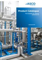
ASCO CO
2
Production Plants
Dimensions in mm
Capacity
A
B
C
D
70kg/h
(154 lb/h)
Skid mounted towers 4‘445 x 7‘670 x 4'800 (L x W x H)
(175 X 301.97 X 188.98 in)
160kg/h
(353 lb/h)
11‘920
(469 in)
5‘735
(226 in)
9'960
(392 in)
2‘130
(84 in)
285kg/h
(628 lb/h)
11‘078
(436 in)
6‘566
(259 in)
10'160
(400 in)
2‘280
(90 in)
500kg/h
(1'102 lb/h)
11‘807
(436 in)
5‘820
(229 in)
11'913
(469 in)
2‘410
(94 in)
1'000kg/h
(2'205 lb/h)
17‘985
(708 in)
8‘380
(330 in)
17‘050
(671 in)
3‘450
(136 in)
1'500kg/h
3'307 lb/h
Dimensions according to customer requirements and space available
2'000kg/h
4'409 lb/h
Schematic layout of typical ASCO CO
2
Production Plant
Diagram shows process streams only. Actual plant configurations may vary.